
Click to see a video
You can both start and end a valve with a stop end. In the start duct dialog box you will find the option free with Stop end, and you will find the same in the end duct dialog box.
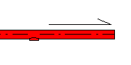
See video of a duct with a stop end in both start and end.
It is possible to define a hole in stop end. To manage this, use a so-called special tee
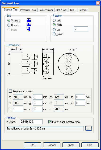
Special tee.
f = number of vertical rows, max 2
h= diameter / width top row
g= height top row. For circular diameter, set this field to 0
r = number of holes in top row
d= diameter/width bottom row
c = height bottom row, For circular diameter, set this field to 0
l = number bottom
m= distance from external duct to first hole in top row
e= distance from external duct to first hole in bottom row.
The next example displays a rectangular duct 1000x500 with a stop end with f) 2 vertical rows, h)315mm dimension top row, r) 3 hole top row, d)200 width bottom row, c)150 height bottom row, l)4 hole button row
Click to see a video
A duct can change dimension or shape anywhere. Both from rectangular to circular and vice versa. This is done by inserting a transition.
![]()
Transition in duct.
A reducer can be inserted while you are drawing the duct, or afterwards. If you want to insert the reducer while you draw, you will find the component in the pop-up menu (click the right button)
![]()
Reducer while drawing ducts.
Reducers can be centric or eccentric, both sideways and upwards/downwards. See video for different reducers.
Bend is the only component that cannot be inserted in a an duct section after it has been drawn. This must be inserted while the duct is drawn. Bend come automatically with a change of direction, and if you want a bend with a special angle, or upwards/downwards, this must be selected from the pop-up menu (click the right mouse button)- see also chapter 8 about pipes.
Rectangular bends have 3 different shapes. Round radius externally and internally, round radius internally but not externally, and no radius either internally or externally.
You will find all these types in the product database.
Click to see a video
If a rectangular duct is twisted and runs vertically, this must be adjusted under the flag ”Direction and position”. For vertical ducts, vertical value must be 90 for ducts running upwards, and -90 for ducts running downwards. If you set the horizontal value to the angle with which the duct is to be twisted, this will be correct.
Example of a twisted duct.
See chapter 4 DWG import, and then chapter 8 Pipe drawing.
You can decide the alignment of a duct while drawing. This reference will be to the left or to the right. Up and down has not yet been included in the DDS-CAD.
Alignment can be decided as you start a duct, or while drawing. In the start duct dialog box you will find the tab ”Alignment”
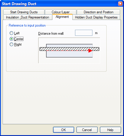
Alignment in start duct dialog box.
While drawing the duct, you will find this in the pop-up menu (click the right mouse button)
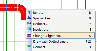
Alignment while drawing the duct.
If you want the reference outside the outer edge of the duct, set this value in the field ”Distance from wall”
You will find the arrows in the same component group as the air handling units.
Four-way throw arrows added to grille.
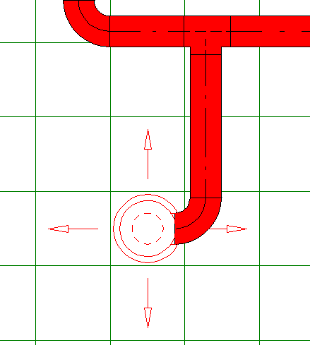
There are two ways of copying sections. One of them you will find in the toolbox, assuming that you have started a duct from a tee/hole, and ended with either a valve or a stop end
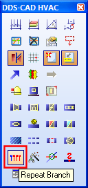
Copy & Repeat Branch.
If you have started from an air terminal and then connected to a duct section, this function will not work.
The other option must be started from DDS-CAD pressure loss calculation. This will include all sections followed by the basis, also through storeys.
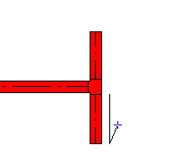
DDS-CAD has 3 different tees. All three can be inserted while the duct is drawn, but only one can be inserted afterwards.
While drawing the duct you can insert a tee by means of the pop-up menu (click the right mouse button) and select Special Tee
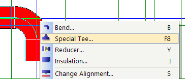
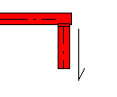
From the right-click context menu.
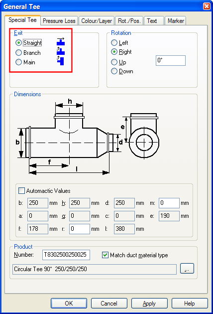
Properties for Tee.
If you insert a tee while drawing, you will get the following options
|
Straight - The tee is inserted and the duct continues drawing in the same direction as before. |
|
Branch - The tee is inserted and the duct is then drawn from the new branch. |
|
Main - The tee is inserted at the end of the duct and you can continue drawing in either direction. |
If you insert a tee after having drawn the duct, only the option Straight is available.
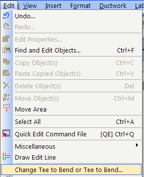
From the menu Edit - >Change Tee to Bend or Bend to Tee, you can change bend to tee and vice versa.
< Previous Section - Next Section >